Dash Movement
In my 2006 Bounder 35E, I noticed the passenger-side window moving up and down relative to the dash as I drove. After putting some blue painter's tape at various points for reference, I determined that the dash was not moving relative to the floor, but the top of the dash was moving up and down as much as 3/4" relative to the side wall of the coach (or vice versa).
This movement was accompanied by a loud squeak from the A-pillar trim and I could see the bottom of that trim flexing as the top of the dash moved relative to the wall. At rest, the L-shaped bottom of the trim was bent up and the trim was very difficult to remove or install because of the tight fit.
After searching the internet and getting some tremendously valuable help from the folks at the IRV2 Forums, and the Yahoo Fleetwood and Bounder user groups, I learned a lot about the connection between the Bounder coach and chassis.
Things to check
Here are a couple of things to look at to see if you have a problem:
The Front Bracket
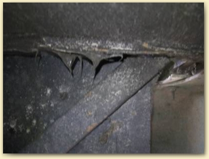
If you own a Fleetwood RV (and perhaps other brands as well), even if you don't have the symptoms I've described, I'd recommend taking a look in the engine compartment. Just in front of the firewall on both sides of many gas-powered Fleetwoods, there is a vertical bracket, screwed to the coach wall. This is the only support for the front end of the coach forward of the support-tube described below. On mine, the bracket is fastened to the coach wall with hex-head screws. If you look closely at the pictures below, you can see that all the screws on mine are missing or sheared off. I was also missing a few screws on the driver's side.
Note also the wire bundle at the right. This will be in your way when you work on the bracket. It's held by a black retainer near the bottom. The retainer is fastened to the firewall with a single sheetmetal screw on the back side that you can't see (thanks Fleetwood — they could just as well have put the screw on the other side). On mine, the sheetmetal screw has a 5/16 head. A long-handled nut driver comes in handy here. After removing the screw, I held the bundle out of the way with a strip of blue painter's tape that I ran around the bundle and then outside and taped to the front of the coach.


On my bounder, there are seven screws on each side. Check all of them with your fingers to see if any are missing or loose. If you look closely at the bottom of the pictures above, you may also see that the bracket on mine is about 3/8" higher than it should be relative to the coach wall behind it. I think this is because the missing screws have allowed the whole front corner of the coach to sag by that much. The only other support point for the coach is the support tube (described below) behind the firewall, just forward of the front tire.
The Support Tube
I've seen this referred to as the "support tube" but don't know if that's the official name. It's a triangular structure made out of square steel tubing in front of both front wheels. There's a vertical tube welded at the top and bolted to the chassis at the bottom. It has a square tube welded to it at a 45-degree angle going up to the top brace. On the outside end, a piece of angle iron is welded to the back of the tube. This angle iron is what actually supports the coach body.
Others have reported cracks or compression of the tube, splitting, or a broken weld where the angle iron is attached. I don't have any of those problems, although it does look like the angle iron has bent down some in the back and the top brace may be bent down somewhat at the right end. The straight white section at the far upper right-hand corner of the first picture below (above the curved fiberglass of the body) is the bottom of the coach body. I don't know if the brace is supposed to extend under it, but obviously it doesn't on mine.

Update I recently had to do this job over again and I learned a few things. Be sure to see the upate at the end of this page.
Stuff I Used
I got everything I used here at Home Depot, but any good hardware store should have the same stuff.
The original screws are #12, but obviously they didn't do the job so I used 1 1/4" #14 self-tapping, self-drilling sheetmetal screws from Home Depot. The package held 25 and I have 5 left. I could just as well have used 1" screws since the aluminum plate behind the bracket is fairly thin and there's nothing of substance behind it. In the picture, you can also see the 3/8" nut-driver drill attachment I used to put them in with.
It's very hard to get a standard drill on them so I used a cordless 18V right-angle drill. Be careful because even a cordless drill can strip the threads if you don't stop it in time. Once I figured that out, I used the drill to start them and hand tightened them with a socket wrench. Make them snug, but don't overdo it — they're going into aluminum. Some of the holes had broken screws in them but the self-threading screws went in anyway. I also added some extra screws in between the existing ones and added some cross braces for more support (see the photo at the bottom of this page).
For the new ones, I drilled a pilot hole a little smaller than the shank of the screws (I think I used a 5/32 bit). You'll want to get a new drill bit or two designed to go through hard steel, otherwise, you'll be drilling all day. I used cobalt bits. For some of them, even a right-angle drill won't be going straight on and the bit will want to walk on you. I tried using a punch to start things, but it walked too. You just need to be patient and have a good two-handed grip on the drill.

Here's another tip: if you're working on grass, as I was, put some cardboard down so you can find any dropped screws or tools. The last thing you need is a big self-tapping sheetmetal screw stuck in one of your tires.
I also put Loctite Red on the threads to help keep them from coming loose. Warning to old-timers: Loctite Red and Loctite Blue now both come in a red tube (go figure). The Red is for permanent installations. Let's hope that's the case here. The 5/16 nut driver was used to remove and install the screw holding the wire bundle in place.


Because the coach and bracket were not lined up, I needed to jack up the coach without lifting the dash. If you are only missing some of the screws, you can just put the new screws in without jacking anything at all. I tried various jacking points, but all lifted both together. I finally fabricated a jacking post out of a pine 2 x 4, an oak 1 x 4, and an angle bracket to lift just the coach. The angle bracket was with the deck hardware at Home Depot. I had to shape the end of the post so it would not touch the black support tube. I made it just long enough to reach the top of a bottle jack sitting on a 2 x 12. You could also make it longer and just retract the front jacks, but I think the bottle jack gave me better control. Here's the post (the job is a little crude because I didn't have a chisel and had to use a circular saw and a big screwdriver):


The shots below show the post in place from below. The first one is from the engine compartment, the second one is from the wheel well. Be sure the metal angle bracket is above the curved fiberglass of the lower coach panel. The top of the post sits about 3/4" below the bottom of the two-inch thick black panel that's behind the bracket with the screws in it. That panel contains the aluminum piece that the screws go into. I imagine that they used aluminum to reduce the weight although I'm not sure it was a good choice.

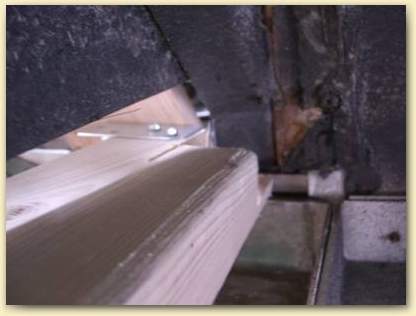
To bridge the gap between the top of the jacking post and the bottom of the black panel, I used an oak 1 x 4 I bought to install as a stabilizer under the dash. I plan to re-use the metal angle bracket there too. I inserted the 1 x 4 through the hood. You'd think someone would have to hold down the far end of the 1 x 4 while you jack (and it's probably a good idea), but I did the job alone and it stayed put. You can see the blue painter's tape I used to hold the wire bundle out of the way.
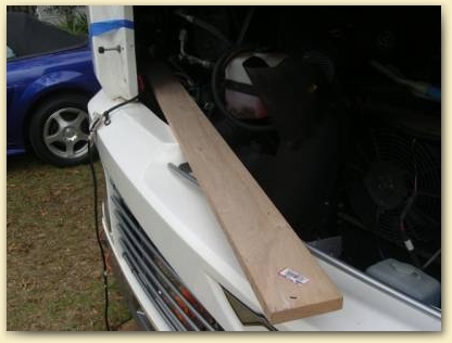

Notice that I removed the hood. It really needs to come off to do this job properly. To remove it, you need to take out the two bolts on each side that hold it to the coach. This is really a two-person job because when you remove the second bolt on one side, that side will drop and potentially bend the hardware and damage the front of the coach. I've done it solo, but I don't recommend it. The bolts are in a slot so the hood can be adjusted up and down. Mark the position with a pencil before loosening the bolts (although there's probably a dirt line that will show where it goes). Here's a tip on replacing the hood — again, a two-person job: there's a large bolt with a rubber bumper on the end next to the hood hardware, when you're trying to replace the nut on the back of the hood hardware, it's easy to mistake that bumper bolt for the hood hardware bolt and try to put the nut on it. It won't fit and you can spend quite a while trying to get the threads to start and questioning your mechanical ability.
Here's a shot (below) of the 1 x 4 and the jacking post together taken from below the engine compartment. Note that the 1 x 4 is above both the upper and lower fiberglass sections of the coach body. This is critical. The body panel would almost certainly break if you tried to lift the coach by it. You want to lift the black panel behind the bracket only. In the first picture, you can see that nothing is lifting the end of the black support tube in the center of the picture (that's the reason for the notch in the jacking post) and nothing is lifting either of the two white fiberglass panels.


Here's a shot of the finished job. You can see two cross braces I inserted for good measure. These are the thickest straps I could find in the decking department (with the joist hangers, deck brackets, etc.). They're much longer than they need to be and hang over the front of the panel. In hindsight, I would have used "mending plates" found at Home Depot with the cabinet hinges. They're shorter and much thicker and stronger. I may replace my cross braces with them if I see trouble or if they "sing" when I travel.

When I was finished, the A-pillar trim swung in with room to spare so I definitely raised the front corner of the coach by a good 3/8" relative to the dash. I noticed that when I put the long bottom screw in the trim, it pulled the top of the dash up significantly. I plan to put a brace (the oak 1 x 4) underneath the dash inside the coach to hold it down. As a side note, when I tried to put the trim in earlier, I put a tiny hole in the dash. I took the cover off the dash fuse compartment to Home Depot and had them mix up a flat latex paint sample in that color (about $2.95) and filled the hole with it using a small artist's paintbrush. The hole is almost invisible now. My fuse compartment cover had some really nasty sticky glue on the back of it, so be careful if you remove yours.
I did the job in a single day (not counting purchasing the hardware). It would have been much faster if only some of the screws were missing. It's not all that difficult, although it's hard on your back because you have to get in some pretty unnatural positions. You need to hold the drill in place with one hand and put pressure on the back of it with the other hand. Your upper and lower body will be at close to a ninety degree angle at that point and you'll probably end up with some bruises on your chest and arms. A mechanic friend once told me that, where he works, they get the smallest guy in the shop to stand up inside the engine compartment for jobs like this. I'm a little big for that, but if you're on the small side, you might try it. If you've got lots of time on your hands, you could also remove the lower part of the front of the coach — that would make it easy.
Thanks again to all the great people who helped me on this. I couldn't have done it without them.
Update
I recently had to re-do this job because when I did it, I didn't know enough to check the screws under the trim piece on each side of the rig (see the pictures below). These screw into the floor of the rig and I've learned that they tend to shear off *before* the ones in the engine compartment do.
If you pull out on the bottom of the trim piece, it will come out to about 45 degrees and you can check the screws. If they're broken or missing you can pull straight out on the trim to remove it and put new screws in. Important: If things have sagged, you'll want to jack up the shell of the rig before putting the screws in.
A number of the side screws were broken off. Rather than drill them out, I just put new ones in different locations. I used larger screws with bigger heads (which have to go in a little higher in order to get the trim back on).
In order to re-do the ones in the engine compartment, I took the whole bottom half of the front off. This went much better than the method I describe above. Here are the steps I followed:
- With a helper, remove the hood as described above.
- Disconnect the headlight connectors — some come straight out, some unscrew.
- Put a support under the bottom of the front end.
- Remove the grill hardware, but photograph and/or mark it first so you can get the angles right when it goes back in. (
- Remove all screws except for the ones holding the upper and lower half together.
- Have a helper hold the lower front end in place while you remove the remaining screws and remove the piece.
Taking off the front end means you can put a board under the rig's shell and jack it up without bothering to fabricate a special piece like the one described above. It also means you don't have to be a contortionist to get to the screws, and you can use a regular drill and put more muscle into the job. It's well worth the time you spend taking the front end off.
More Photos
Site visitor, Anthony Podbevsek, was kind enough to send me some more pictures that you might find helpful. His braces look much stronger than the ones I did. Notice that Anthony has used a mixture of screws and steel pop rivets.
Outside Trim


Engine Compartment


Thank you for visiting BobsGuides.com
— Bob Ray


